Steel Space Frames
Steel space frames
Steel space frames have some interesting characteristics, including an extreme geometry adaptability – even to complex shapes – and a very low weight in relation to lights. Such characteristics could be improved thanks to the possibility of optimizing each individual rod sizing.
The weight saving implies their natural predisposition to be used in earthquake zones thanks to the lower inertial forces induced by the earthquake.
Steel space frames are supported by software for structural analysis, section verification, rods and nodes optimization, drafting of CAD/CAM files, and on-site assembly drawings.
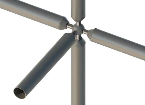
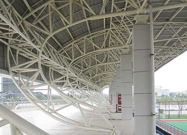
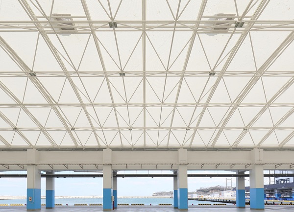
A space frame is made up of spherical nodes to which the individual rods of upper and lower members and the diagonal rods are fixed with a screw. Thus, the structure appears as a sequence of square-based tetrahedrons after mounting.
More specifically, nodes are made by forged steel spheres and suitable for connecting the various rods. Nodes will be drilled and threaded depending on bolt diameters.
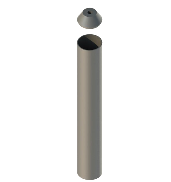
The surface in contact with the rod end will be mechanically leveled. Diameter of spheres will be sized depending on structural and dimension requirements in relation to loads and structure geometry. Rods will be made by steel tubes for structural uses, and hot-forged cones will be welded to the tube ends.

Spherical node of tetrasteel system for building steel space frames
Therefore, HBK construction system is made up of:
Rods are made by S235/ S355 steel tubes of circular section; standard diameters range from a minimum size of 48mm (1.89in)to a maximum size of 324mm (12.76in), with variable thicknesses based on the structural element specific need.
Spherical nodes are made of hot-molded C45 steel; standard nodes have a diameter ranging between 70mm (2.76in) and 418mm (16.46in).
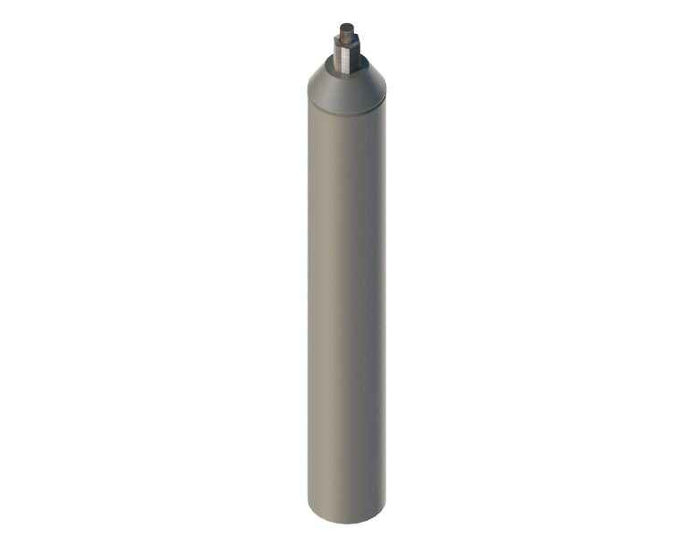
Cones are welded to the tube ends, thus enabling to reduce interferences by fixing to spherical nodes (and use smaller spherical nodes, as well).
Connection between sphere and rod is ensured by a cheese head screw inside the tube, which fastens in the provided node hole by turning a non-threaded hex nut fixed to the screw with a pin. In compressed rods the nut will ensure the stress transfer between rods and spherical nodes. Bolts, screws and hex nuts will be sized depending on structural and dimension requirements, in relation to loads and structure geometry.
The HBK system enables to build – thanks to the possibility of individually sizing each element – very statically efficient and extremely light structures with a great versatility and adaptability to complex geometries. The system is based on a total prefabrication of elements in the workshop and on-site assembly according to an accurate procedure for nodes and rods identification that enables to drastically speed up the on-site work phases.
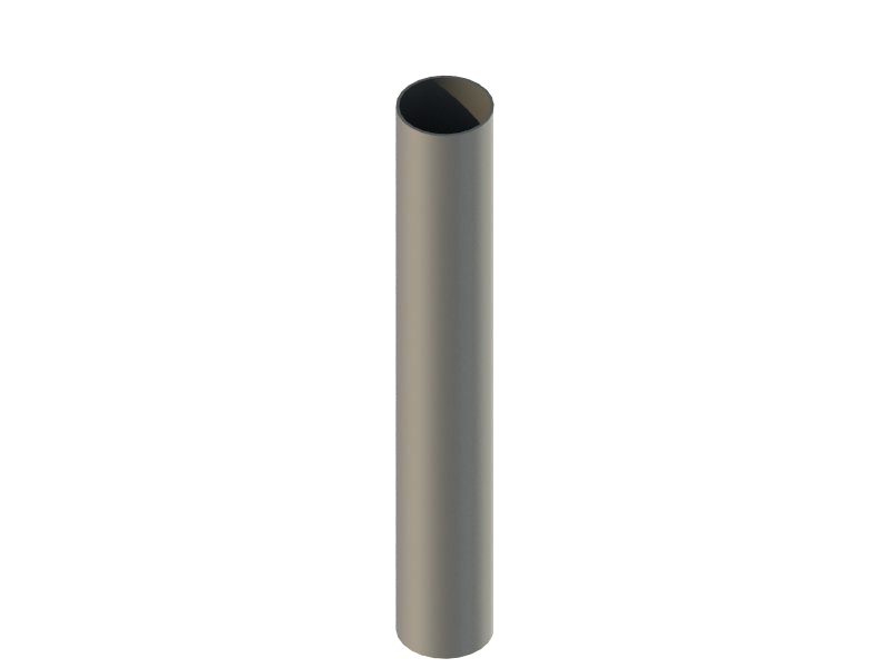
Rods are made by S235/ S355 steel tubes of circular section; standard diameters range from a minimum size of 48mm (1.89in) to a maximum size of 324mm (12.76in), with a variable thicknesses based on the structural element specific need.
Cones are welded to the rod ends. Welding is performed by an especially designed machinery. It has a specific housing for proper cone positioning, the welding torch is fixed and turns the tube until welding is completed.
Nodes are made up of C45 steel solid spheres resulting from a hot molding process; standard nodes have a diameter ranging between 70mm (2.76in) and 418mm (16.46in).
Spheres are appropriately shaped, faceted, and threaded through a 5 degrees of freedom machining center.
S355 steel cones are welded to the tube ends so to be fixed to the spheres, thus reducing interferences (and using smaller nodes). Cone and rod are welded with a fully restoring connection automatically performed by a MAG (Metal-arc Active Gas) system.
Cones are forged with a hot molding process.
Mounting is carried out in several phases.
Ground Mounting:
First, some meshes of the lower member are mounted by fixing rods to nodes and tightening the screws in the provided sphere holes;
Then, the first diagonals are mounted using the same method described above, thus creating a first tetrahedron;
Finally, a second tetrahedron is mounted and upper member spheres are connected by the rods;
This sequence is repeated until all spheres and rods of the structure are mounted.

Overhead Lifting:
After the ground mounting phase, the overhead mounting needs to be performed.
The structure must be secured with textile ropes of appropriate capacity.
Lifting shall occur in two steps:
First, the structure is lifted from the ground by few centimeters (inches) and kept hanging for a few minutes so to observe its performance and check its perfect flatness.
If there are no issues with the first lifting, the final lifting and positioning of the structure can be carried out.

Steel space frame lifting
If the structure size prevents mounting in a single element, it shall be performed by segments.
Mounting methods of individual segments are similar to the ones described above.
INQUIRY
RELATED PRODUCTS
Categories
Latest News
Contact Us
Contact: Mr.Lu
Phone: +86-51668601029
E-mail: hbktech@163.com
Whatsapp:86+15152106218
Add: 1412, Building 2, Vanke Huaihai Xintiandi, Block 3, Quanshan District, Xuzhou City, Jiangsu Province