Case Analysis of Stadium Structural Design
01
Project Overview
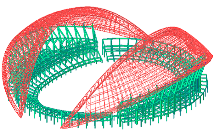
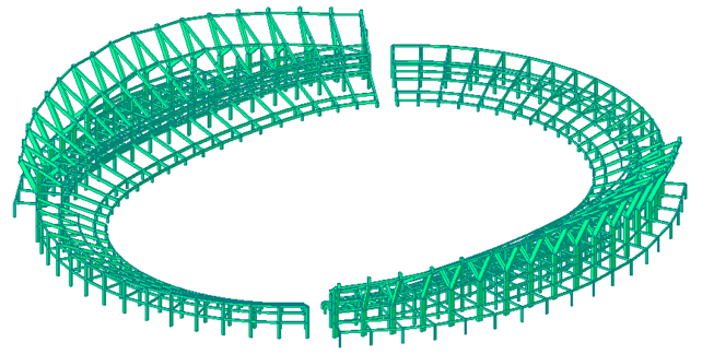
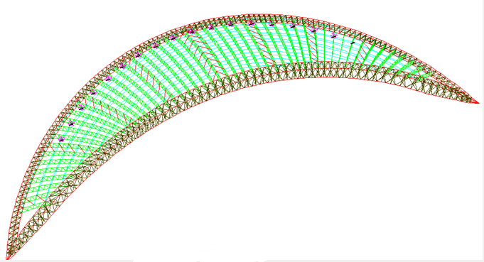
The main structure of this project adopts reinforced concrete frame structure, the roof is Steel structure, the roof plane shape is crescent-shaped, and the roof steel structure consists of a ground-to-ground inner arch with a span of 330m, an outer arch supported on the top of the concrete column, and a truss connecting the two arches. The span of the outer arch is 89m, located between the 9-axis support and the arch foot.
Overall model of stadium structure
Lower concrete stand
Roof steel structure layout
02
Roof steel structure system
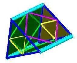
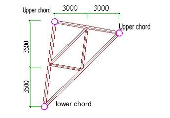
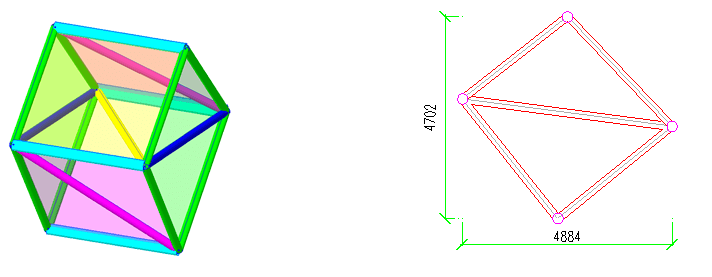
The span of the inner arch is about 330m, and the height and width of the structure are shown in the figure below. In order to facilitate the connection with the truss, the bar arrangement of the transverse section of the inner arch structure unit continues the truss bar arrangement, and the chord and plane diamond web bar are used in the longitudinal direction. As shown in the figure below.
Three-dimensional diagram of the inner arch structure unit
Plan view of the inner arch structure unit
The total span of the outer arch is 330m, and the middle part of the arch falls on the column top support, with a support spacing of 12m. The maximum span is distributed at both ends, with a plane span of 79m. The height and width of the structure are shown in the figure below.
External arch structural unit
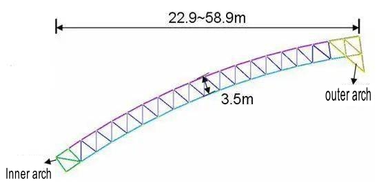
A total of 26 trusses are arranged, with a maximum span of 58.9m, a minimum span of 22.9m, and a truss height of 3.5m., as shown in the figure below.
Arrangement of single truss rods
03
Calculation and analysis software
Midas/Gen software is used for overall structural analysis.
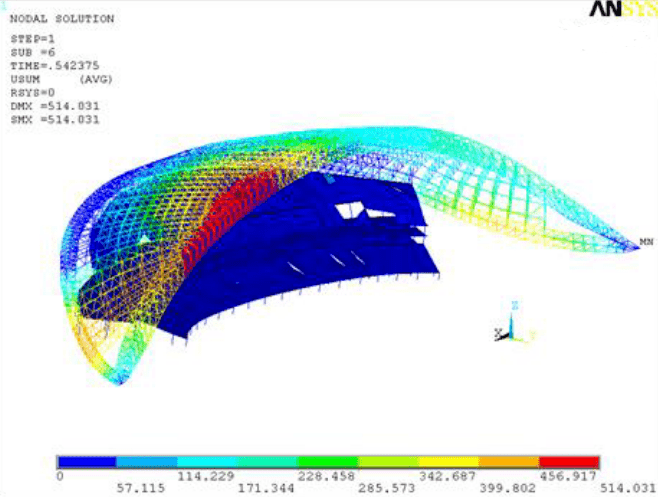
ANSYS software is used for stability analysis.
04
Loads and load combinations
1 Structural self-weight, magnified by 1.1 to consider the weight of the plug board.
2 Roof panel load: 0.5kN/m2.
Local horseway and lighting load: 2kN/m.
3 Roof live load 0.5kN/m2.
4 Roof snow load 0.40kN/m2.
5 Wind load
5.1 Basic wind pressure: 0.6kN/m2, ground roughness Class B.
5.2 The roof shape coefficient is determined according to the wind tunnel test results.
5.3 The wind vibration coefficient is determined according to the numerical simulation results provided by the wind tunnel test unit.
5.3 The wind load height coefficient is determined according to the actual height.
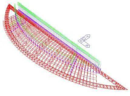
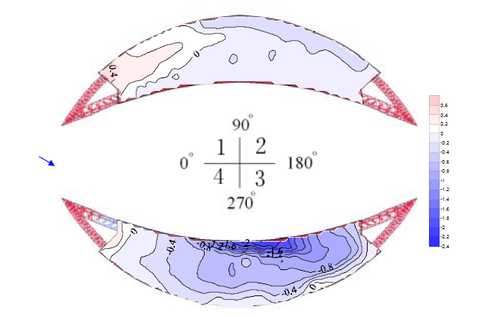
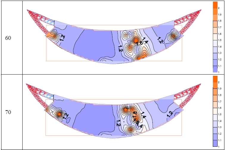
The detailed wind load shape coefficient distribution is detailed in the wind tunnel test report. The report gives the wind load shape coefficient of 0 to 90 degrees according to the symmetry of the structure. The figure below shows the wind load shape coefficient distribution at a wind direction angle of 30 degrees. The wind load shape coefficient on the roof canopy is the largest at this wind direction angle.
Horseway load distribution diagram
30° system coefficient distribution diagram
60° and 70° system coefficient distribution diagram
6 Temperature action is determined as follows:
① Assume that the closing temperature is 15ºC~20ºC
② The temperature load of the concrete structure is ±10ºC
③ The temperature load of the steel structure, the inner arch is heated by 40 ºC, the other components are heated by 20 ºC, and all are cooled by 20 ºC
④ The temperature load during the steel structure construction phase, all steel structure components are heated by 50 ºC.
7 The earthquake action meets the three levels and two stages.
05
Analysis results
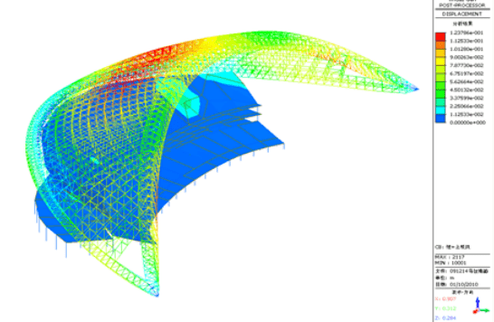
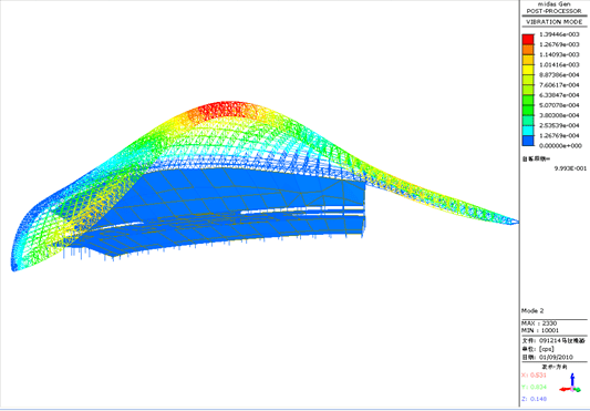
Since the stadium roof and the lower structure are axisymmetric structures, half of them can be taken for calculation and analysis, and the results of this part can be used as the design basis for the other symmetrical half. The analysis results are shown in the figure below.
Deformation diagram
Shape diagram
Overall stability
RELATED NEWS
- Construction process of steel structure workshop 2024-05-09
- Reasonable design of glass dome to prevent high temperature of building 2024-05-08
- I-Beam and H-Beam 2024-04-16
Categories
Latest News
Contact Us
Contact: Mr.Lu
Phone: +86-51668601029
E-mail: hbktech@163.com
Whatsapp:86+15152106218
Add: 1412, Building 2, Vanke Huaihai Xintiandi, Block 3, Quanshan District, Xuzhou City, Jiangsu Province
